When optical surface inspection needs telecentric imaging
When Optical Surface Inspection Needs Telecentric Imaging
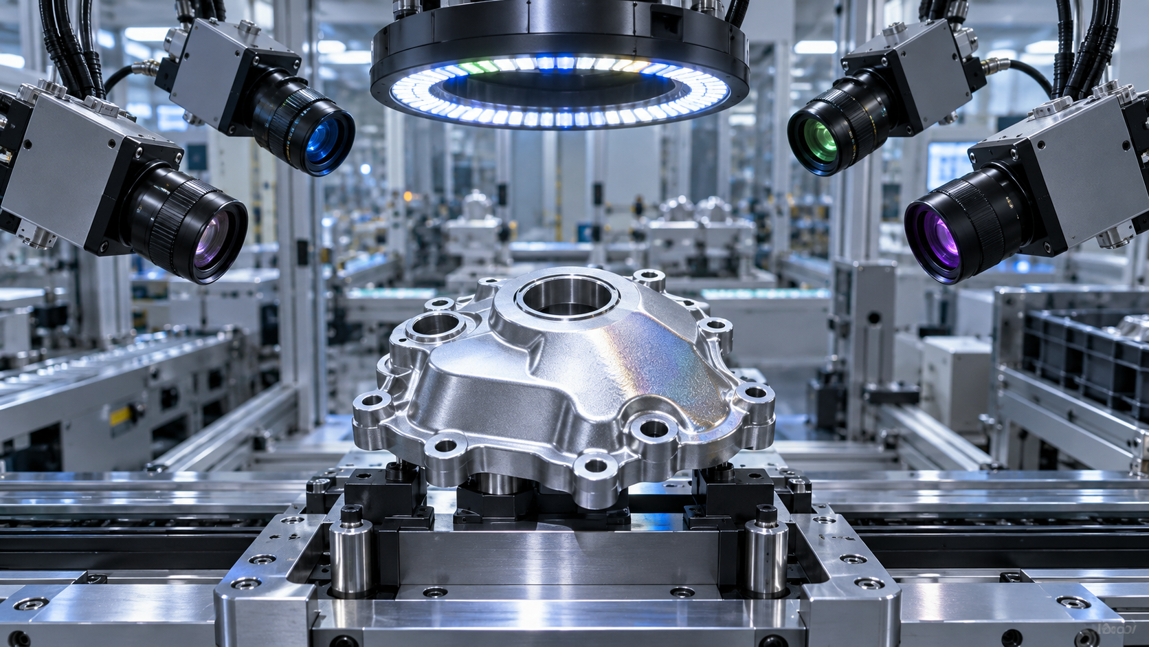
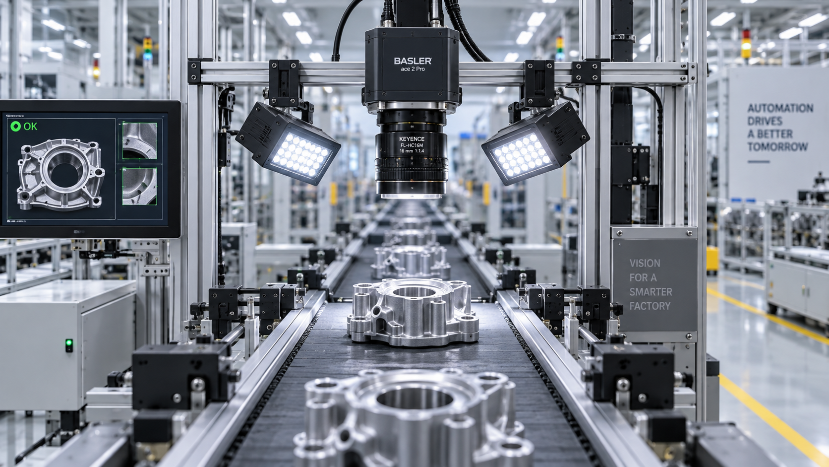
Optical surface inspection becomes much less forgiving once a system must make reliable decisions across changing part heights, curved edges, recessed features, or a wide field of view. A conventional lens may produce images that look sharp and visually acceptable, yet still introduce a measurement error large enough to confuse a dimensional check, inflate a defect size, or make one production batch appear different from another.
That is the point at which telecentric imaging deserves serious consideration. It is not a premium lens category that automatically improves every machine vision application. In fact, it can add cost, physical length, lighting constraints, and integration complexity. But where optical surface inspection depends on stable magnification and trustworthy edge geometry, a telecentric lens often solves problems that software calibration cannot fully remove.
The practical question is not “Is telecentric optics better?” It is: “Will the inspection decision change if the part moves slightly in depth?” If the answer is yes, the imaging system should be assessed from a telecentricity perspective before investing further in cameras, algorithms, or illumination.
The hidden measurement problem in ordinary imaging
Most standard industrial lenses are entocentric. They see an object in a way that is broadly similar to the human eye: features farther from the lens appear smaller, and features closer to the lens appear larger. This perspective is useful in many applications, including general assembly verification, barcode reading, robot guidance, and presence-orientation checks.
For precision inspection, however, perspective can become a source of uncertainty. A stamped metal part that sits slightly higher on a conveyor may appear marginally larger than the same part in the previous cycle. A hole edge may shift in the image when the workpiece is tilted. The apparent width of a chamfer, coating boundary, seal line, or laser-marked feature can change even though the physical feature has not changed.
These effects are especially troublesome when a vision system is expected to do two jobs at once: identify surface defects and confirm geometry. Surface inspection is often discussed in terms of contrast, resolution, and lighting. Those matter, but they do not eliminate geometric error. If the defect acceptance threshold is close to the variation introduced by changing object distance, the system can generate unstable pass/fail results.
Telecentric lenses are designed so that the chief rays are substantially parallel on the object side, image side, or both. In object-space telecentric imaging, magnification remains comparatively stable as the object shifts within the lens’s usable depth range. The camera therefore sees a feature more as a dimensional projection than as a perspective view. This is why telecentric optics are common in gauging, metrology-oriented vision, semiconductor-related inspection, precision electronics, and component measurement.
When telecentric imaging is genuinely necessary
A telecentric lens is most justified when part-height variation is unavoidable and dimensional tolerance is tight. This can occur even in apparently simple production lines. Trays may not hold every component at the same elevation. A fixture can introduce small but repeatable variation. Thin parts may bow slightly. Molded components may have edge features that sit above or below the reference plane. In these situations, recalibrating the system for one nominal working distance does not address the real production condition.
The same applies to edge-based inspection. Many systems rely on edge position to measure a gap, diameter, lead pitch, slot width, or printed feature. Under entocentric imaging, the edge may be detected cleanly but still represent the wrong physical location because the apparent boundary changes with depth and viewing angle. A telecentric lens does not make every edge easier to detect; illumination still determines whether the edge has sufficient contrast. It does make the measured geometry less dependent on where the part happens to sit.
Another strong use case is inspection of cylindrical, stepped, or partially raised components. Consider a part with a top surface that must be checked for scratches and a surrounding rim that must be measured. A conventional lens may cause the rim to appear wider or narrower depending on the part’s axial position. If the inspection system evaluates both scratch location and rim width, perspective error can make root-cause analysis unnecessarily difficult. The operator may suspect process instability when the actual issue is optical geometry.
Telecentric imaging is also worth evaluating when machine vision results must be compared between stations, shifts, or sites. A measurement model that is sensitive to setup distance can be difficult to transfer, particularly if each line has slightly different fixtures, camera mounts, or maintenance practices. Stable magnification reduces one category of variation, though it does not eliminate the need for proper calibration, mechanical repeatability, and controlled lighting.

Surface defects are not all telecentric problems
It is easy to over-specify telecentric optics when the real problem is illumination. Fine scratches, shallow dents, coating streaks, residues, orange peel, and micro-texture often depend more on lighting angle and spectral response than on lens geometry. A diffuse dome light may reveal contamination but hide a faint scratch. Low-angle dark-field illumination can make that scratch obvious while exaggerating harmless texture. Coaxial lighting can work well on relatively flat reflective surfaces, but it may suppress the contrast needed for certain defects.
If the task is simply to find obvious foreign material or severe cosmetic damage on a flat, consistently positioned surface, an entocentric lens may be entirely adequate. The decision changes when the system must assign a physical size to the defect, verify its distance from an edge, or reject parts based on dimensional limits that are close to the measurement uncertainty.
A useful distinction is this: telecentric optics manage perspective and magnification behavior; lighting manages visibility; image processing manages feature extraction. None of these substitutes fully for the others. A high-resolution camera attached to a non-telecentric lens does not become metrology-grade by software alone. Equally, a telecentric lens cannot rescue a low-contrast surface if the illumination scheme is poorly matched to the material.
A practical evaluation framework before selecting a lens
The most productive evaluation starts with the measurement risk, not the lens catalogue. Teams often begin by selecting a camera sensor and then search for a lens that covers the field of view. That sequence may work for general inspection, but precision optical surface inspection benefits from defining the inspection decision first: what must be detected, measured, located, and documented?
It is also important to calculate the required spatial resolution realistically. Pixel count by itself is not a measurement specification. The relevant question is how many pixels represent the smallest feature that must be detected or measured, after allowing for contrast, lens performance, motion blur, and the chosen inspection algorithm. In many real projects, a system appears adequate on a static sample but becomes unreliable at production speed because exposure time, vibration, or lighting stability was not considered early enough.
Lens resolution should be matched to camera pixel size and the selected magnification. A very high-resolution sensor can expose limitations in the lens, particularly near the edge of the image circle. Conversely, paying for an optically demanding lens may not yield usable value if the camera, lighting, or mechanical setup cannot support the intended measurement repeatability.
Object-side, image-side, and bi-telecentric choices
Not every telecentric lens behaves in the same way, and product descriptions can create confusion if the application requirement is not clearly stated. Object-side telecentric lenses are usually the relevant starting point for dimensional inspection because they reduce magnification variation caused by changes in object distance. Image-side telecentric designs can be useful where the optical path must match the camera sensor geometry. Bi-telecentric lenses combine both characteristics and are often considered for demanding metrology applications where distortion control and measurement consistency are central concerns.
The right choice depends on more than the word “telecentric” in a specification sheet. Inspect the stated field of view, magnification, working distance, distortion behavior, numerical aperture, depth of field, sensor compatibility, and telecentricity specification. Suppliers may express some of these parameters differently, so direct comparison requires care. A lens with a suitable nominal field of view may still be a poor fit if the required object height range sits outside its effective operating condition.
Physical integration matters too. Telecentric lenses can be larger and heavier than conventional lenses of comparable field coverage. This affects camera brackets, guarding, maintenance access, and vibration sensitivity. In a compact inspection cell, the available working distance may become the deciding constraint. It is better to identify that conflict during concept design than after a camera enclosure and illumination assembly have already been released.
Common mistakes that make a good lens look ineffective
One recurring mistake is treating telecentricity as permission to accept poor part presentation. Telecentric imaging reduces sensitivity to depth movement; it does not make a badly tilted, vibrating, or rotating part geometrically perfect. If the part can move laterally, rotate unpredictably, or leave the usable depth range, fixture design remains part of the measurement system.
Another is calibrating only at the center of the field. Optical surface inspection frequently evaluates features close to corners, edges, or multiple positions across a tray. Calibration and verification should reflect those actual regions. Distortion, illumination falloff, sensor shading, and edge sharpness can all vary across the image. A system that performs well on a central reference target may behave differently on a production part at the edge of the field.
There is also a tendency to specify the smallest possible defect without defining its visual signature. A dark particle, a shallow scratch, a transparent residue, and a small pit may have similar lateral dimensions but require very different optical conditions. Before choosing a telecentric lens, collect representative samples that include acceptable variation, borderline conditions, and known defects where possible. This gives the system integrator something more useful than an abstract defect-size statement.
Where telecentric imaging fits in a broader inspection strategy
In advanced manufacturing, telecentric optics are one component of a larger chain that includes camera selection, illumination, motion control, calibration, software, enclosure design, and traceability. The best results usually come from treating these as connected decisions. A stable imaging geometry can simplify downstream algorithms because the software is not constantly compensating for changing apparent scale. That can be valuable when inspection throughput is high or when a system must remain maintainable for years rather than merely pass an initial demonstration.
For organizations comparing machine vision components, it is useful to review telecentric optics alongside related issues such as lens distortion, optical coatings, sensor sensitivity, illumination wavelength, and production-line mechanical stability. This broader perspective is particularly relevant in sectors that combine laser processing, precision assembly, semiconductor equipment, electronics packaging, and automated quality control. Technical intelligence platforms such as OLES can help frame those comparisons around system risk rather than isolated component specifications.
The clearest selection rule is straightforward: choose telecentric imaging when perspective-driven magnification change could alter a quality decision, a dimensional result, or the comparability of inspection data. If the task is only visual presence checking on stable, flat parts, the additional cost may not be justified. But when optical surface inspection must remain credible across part-height variation and field position, telecentric optics are often not an upgrade—they are the optical foundation the measurement task has been missing.
Recommended News
 Narrowband/IR Cut FiltersHow to Select Dielectric Thin-Film Longpass Filters by Edge Wavelength and AOIDielectric thin films longpass filters: learn how edge wavelength, AOI, polarization, and blocking range affect optical performance—select with confidence.Oct 07, 2026Author:Optical Coating Scientist
 Optical TransceiversHow MSA Standards Help Engineers Select Compatible Optical TransceiversOptical Transceivers MSA standards help engineers verify form factor, host, power, and optical link compatibility. Use this practical guide to select with confidence.Oct 06, 2026Author:Photonics Strategist
 Optical TransceiversCoherent Optical Communication Price: What Drives 400G and 800G Upgrade Costs?Coherent optical communication price explained: compare 400G and 800G upgrade costs, reach, power, compatibility, and lifecycle value for smarter network investments.Oct 05, 2026Author:Photonics Strategist
 Area Scan CamerasHow Multispectral Imaging Inspection Detects Defects Beyond RGB VisionMultispectral imaging inspection detects hidden defects beyond RGB vision, revealing moisture, oil, coating variation, and material differences for smarter quality control.Oct 04, 2026Author:Machine Vision Optical Expert
 Opto-Capital & Vision EconOptical Component Vendor Qualification: A Risk-Based Checklist for Procurement TeamsOptical component supply chain vendor qualification: use a risk-based checklist to assess quality controls, traceability, production continuity, and sourcing risk.Oct 03, 2026Author:Mr. Orion Cross
 Narrowband/IR Cut FiltersOptical Filter Durability: Choosing Dielectric Thin-Film MaterialsDielectric thin film materials determine optical filter durability. Explore how material pairs, deposition quality, substrates, and validation protect spectral performance in demanding environments.Oct 02, 2026Author:Optical Coating Scientist
 Silicon Photonics OPAPhotonic Sensor Design for LiDAR: Key Trade-Offs in Range, Resolution, and CostPhotonic sensor design for LiDAR: explore the critical trade-offs in range, resolution, wavelength, receiver performance, and cost for reliable, scalable sensing systems.Oct 01, 2026Author:LiDAR Systems Fellow
 Optical TransceiversOptical DSP Algorithms: Improving Receiver Sensitivity in Coherent TransceiversDSP algorithms optics improve coherent transceiver receiver sensitivity through dispersion compensation, polarization equalization, phase recovery, and FEC—assess reach, OSNR, and link margin.Sep 30, 2026Author:Photonics Strategist
 Non-linear Optics & ThermalSelecting Low-Loss Infrared Optical Components for High-Power Laser SystemsInfrared optical components low loss: learn how to select materials, coatings, and mounts that protect beam quality, reduce thermal risk, and improve laser uptime.Sep 29, 2026Author:Prof. Kaelen Sterling
 Area Scan CamerasWhat to Evaluate When Sourcing Optoelectronic Sensors for German Factory AutomationOptoelectronic Sensors Germany: learn how to evaluate detection reliability, PLC and IO-Link integration, environmental protection, lifecycle cost, and supplier support for dependable factory automation.Sep 28, 2026Author:Machine Vision Optical Expert
 Area Scan CamerasSelecting Industrial Automation Imaging Cameras for High-Speed Inspection LinesIndustrial automation imaging camera selection guide for high-speed inspection lines—compare resolution, shutters, lighting, optics, and data flow for reliable defect detection.Sep 27, 2026Author:Machine Vision Optical Expert
 PM & Radiation-hard FibersHow Submarine Optical Cables Are Designed to Withstand Deep-Sea Pressure and FaultsSubmarine optical cables are engineered to withstand deep-sea pressure, route hazards, and faults. Explore layered protection, monitoring, and repair strategies.Sep 26, 2026Author:Photonics Strategist
 3D Laser ProfilersTime-of-Flight Technology Standards: Accuracy, Safety, and Interoperability RequirementsTime-of-flight technology standards explained: compare accuracy, laser safety, functional safety, and interoperability requirements for reliable ToF deployment.Sep 25, 2026Author:Machine Vision Optical Expert
 3D Laser ProfilersBeam Diagnostics for M² Measurement: Methods, Accuracy Limits, and Setup ChoicesBeam diagnostics M2 measurement explained: compare ISO-aligned methods, accuracy limits, and setup choices to qualify lasers, reduce risk, and improve optical performance.Sep 24, 2026Author:Machine Vision Optical Expert
![]() Telecentric LensesWhen optical surface inspection needs telecentric imagingOptical surface inspection demands telecentric imaging when depth variation, edge geometry, and tight tolerances affect results. Learn when stable magnification improves accuracy.Sep 24, 2026Author:Machine Vision Optical Expert
Telecentric LensesWhen optical surface inspection needs telecentric imagingOptical surface inspection demands telecentric imaging when depth variation, edge geometry, and tight tolerances affect results. Learn when stable magnification improves accuracy.Sep 24, 2026Author:Machine Vision Optical Expert![]() 3D Laser ProfilersCan 3D surface defect inspection reveal shallow dents reliably?Surface defect inspection can reliably detect shallow dents when sensor choice, repeatability, lighting, and thresholds align. Discover how to validate 3D inspection for production.Sep 24, 2026Author:Machine Vision Optical Expert
3D Laser ProfilersCan 3D surface defect inspection reveal shallow dents reliably?Surface defect inspection can reliably detect shallow dents when sensor choice, repeatability, lighting, and thresholds align. Discover how to validate 3D inspection for production.Sep 24, 2026Author:Machine Vision Optical Expert![]() FMCW Laser SourcesHow lidar module packaging affects thermal drift in FMCW sensingLidar module packaging directly affects thermal drift, chirp stability, and ranging accuracy in FMCW sensing. Explore key design factors for reliable performance.Sep 24, 2026Author:LiDAR Systems Fellow
FMCW Laser SourcesHow lidar module packaging affects thermal drift in FMCW sensingLidar module packaging directly affects thermal drift, chirp stability, and ranging accuracy in FMCW sensing. Explore key design factors for reliable performance.Sep 24, 2026Author:LiDAR Systems Fellow![]() Opto-Capital & Vision EconWhat Should Be Checked Before Accepting a Precision Optical Component?What should be checked before accepting a precision optical component? Explore essential checks for geometry, surface quality, coatings, materials, traceability, and documentation.Sep 24, 2026Author:Mr. Orion Cross
Opto-Capital & Vision EconWhat Should Be Checked Before Accepting a Precision Optical Component?What should be checked before accepting a precision optical component? Explore essential checks for geometry, surface quality, coatings, materials, traceability, and documentation.Sep 24, 2026Author:Mr. Orion Cross![]() Optical TransceiversHow Do Photonic Integrated Circuits Reduce Transceiver Cost?How do photonic integrated circuits reduce transceiver cost? Explore how PICs cut alignment, packaging, and scaling costs for high-speed optical modules.Sep 24, 2026Author:Photonics Strategist
Optical TransceiversHow Do Photonic Integrated Circuits Reduce Transceiver Cost?How do photonic integrated circuits reduce transceiver cost? Explore how PICs cut alignment, packaging, and scaling costs for high-speed optical modules.Sep 24, 2026Author:Photonics Strategist![]() Silicon Photonics OPAIs Silicon Photonics Ready for High-Volume Optical Transceivers?Is silicon photonics ready for high-volume optical transceivers? Explore its 800G potential, packaging challenges, cost drivers, yield, and buyer-ready decision factors.Sep 24, 2026Author:LiDAR Systems Fellow
Silicon Photonics OPAIs Silicon Photonics Ready for High-Volume Optical Transceivers?Is silicon photonics ready for high-volume optical transceivers? Explore its 800G potential, packaging challenges, cost drivers, yield, and buyer-ready decision factors.Sep 24, 2026Author:LiDAR Systems Fellow