When do electro optic systems need faster switching response?
When Do Electro-Optic Systems Need Faster Switching Response?
Faster switching response is essential when electro-optic systems must control light with nanosecond-level precision, preserve signal integrity, or remain synchronized with high-speed lasers, sensors, and communications equipment. The purchasing question is rarely “What is the fastest device available?” A more useful question is whether the complete optical control chain can switch quickly enough, repeatably enough, and cleanly enough for the intended operating condition.
That distinction matters because an electro-optic modulator, Pockels cell, optical switch, or intensity-control assembly can appear fast on a datasheet while the installed system is limited by driver bandwidth, cable reflections, trigger jitter, optical alignment, detector response, or thermal drift. In practical evaluation, response speed is not an isolated specification. It is a system-level requirement tied to pulse width, repetition rate, timing tolerance, optical wavelength, power level, and acceptable contrast between the “on” and “off” states.
For technical teams selecting electro optic systems, faster switching becomes necessary when slow transitions alter the measurement, expose a workpiece to unwanted energy, blur a captured image, create ranging ambiguity, or reduce the usable margin in a communications link. In other situations, paying for extreme bandwidth can add unnecessary driver complexity and integration risk without improving the final result.
Speed matters when the optical event is shorter than the transition
The simplest decision rule is to compare switching behavior with the optical event being controlled. If an optical pulse is only slightly longer than the device rise time and fall time, the system does not produce a clean optical gate. The leading and trailing edges consume too much of the useful window, and the delivered waveform can differ materially from the electrical command.
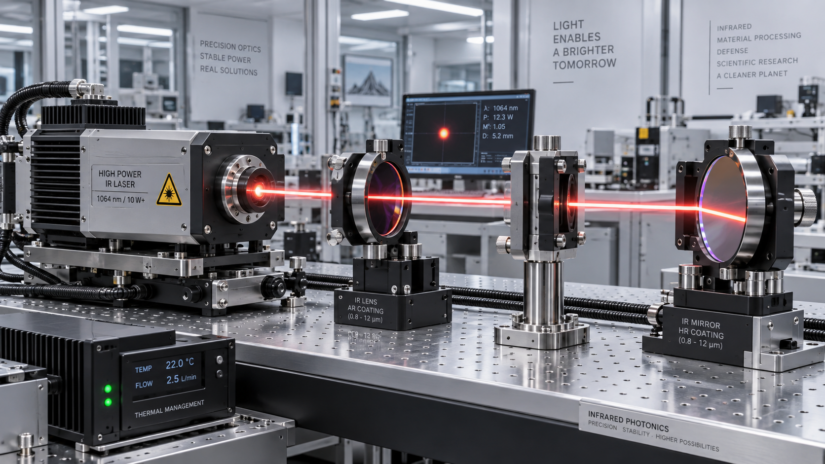
This is particularly relevant in pulsed laser systems. A Pockels-cell-based shutter or pulse picker may need to pass one pulse while rejecting neighboring pulses. If the voltage transition is too slow, partial transmission can occur before or after the selected pulse. In a high-energy or precision-processing setup, that leakage may affect pulse-to-pulse energy consistency, thermal loading, or downstream process control. The optical device may itself be capable of fast electro-optic conversion, but its useful performance depends on the matched high-voltage driver and the timing relationship to the laser source.
The same principle applies to gated detection. When a camera, photodetector, or measurement instrument needs to observe a narrow interval, a slow optical gate broadens the observation window. That can admit background light, unwanted reflections, or signals from the wrong depth range. Faster response is therefore valuable not only for making light appear or disappear quickly, but for defining a measurement window with enough precision to separate useful information from interference.

Applications where switching speed is usually a real constraint
Not every application needs the same response profile. Some systems need rapid edge transitions; others depend more on low timing jitter, stable modulation depth, or reliable operation over long duty cycles. The following situations commonly justify closer scrutiny of fast switching capability.
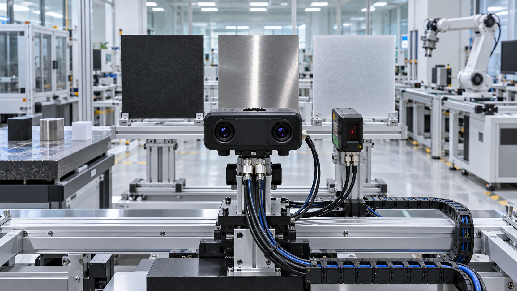
In industrial machine vision, for example, the demand may not come from the camera frame rate alone. A production line can use a short exposure to reduce motion blur, yet still fail to freeze the image if the illumination pulse arrives late or ramps too gradually. An electro-optic shutter or modulator may be part of the answer, but the decision should begin with the allowable optical timing error at the image plane rather than a broad request for “high speed.”
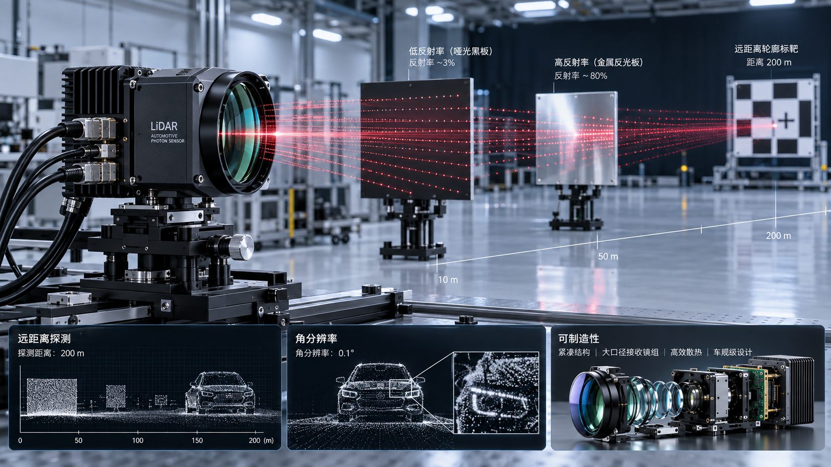
For LiDAR and advanced sensing, the situation is more nuanced. Faster optical modulation can help where timing resolution, pulse shaping, background suppression, or switching between optical paths is part of the architecture. However, it does not automatically improve ranging performance. Receiver sensitivity, SPAD or photodiode characteristics, timing electronics, laser wavelength, optical aperture, and signal processing may be equally limiting. A fast modulator cannot compensate for a detector chain with inadequate timing fidelity.
Do not confuse response time with bandwidth, latency, or jitter
Speed specifications are often compared too casually. Rise time describes how quickly an output moves between defined levels. Bandwidth describes the frequency range over which a device can transmit or modulate a signal within a stated response criterion. Latency is the delay between an electrical command and the optical result. Jitter is the variation in that timing from event to event. Settling time indicates how long the output takes to become stable after a transition.
A system may have a short nominal rise time but still be unsuitable for pulse selection if trigger jitter is large relative to the pulse spacing. It may have wide small-signal bandwidth but inadequate extinction at the desired operating point. It may switch quickly once, then show waveform distortion or drift during sustained operation. These differences are why device-only comparison can lead to expensive redesigns later.
The electrical interface deserves the same attention as the optical component. Fast electro-optic systems operate in a regime where cable length, connector type, transmission-line impedance, grounding, driver output capability, and parasitic capacitance can all reshape the pulse. Ringing can cause multiple optical transitions. Reflections can reduce the effective voltage across the crystal or modulator. Electromagnetic interference can disturb neighboring control electronics. A technically sound selection review should include the modulator, driver, trigger source, interconnects, termination scheme, and diagnostic method as one chain.
When faster switching is not the right priority
There are many applications where moderate switching speed is entirely sufficient. A laboratory beam shutter used for safety interlocking, a slowly changing attenuation control loop, or an optical path selector that changes only between production cycles may benefit more from low insertion loss, high damage resistance, simple control electronics, or stable long-term alignment.
Choosing an ultrafast solution in these cases can create avoidable burdens. High-speed drivers may require careful shielding and power management. Higher-voltage operation can affect enclosure design and safety procedures. Faster devices can impose tighter tolerances on triggering and installation. If the process tolerates a slower transition, a more robust architecture may offer better total system performance.
The right target is therefore not maximum speed. It is sufficient speed with margin. That margin should account for normal variation in source timing, temperature, component aging, control-loop behavior, and manufacturing tolerances. A design that works only under ideal bench conditions is not necessarily suitable for a production environment.
The trade-offs behind a fast electro-optic design
Electro-optic switching technology is selected around several linked trade-offs. Pockels-cell-based arrangements are widely associated with rapid optical gating and can be appropriate for demanding laser control tasks, but the practical system may require high-voltage drive electronics and careful optical alignment. Integrated modulators can offer compactness and high-frequency operation for communications-oriented architectures, while their wavelength range, optical power handling, polarization behavior, and coupling method must fit the wider design.
Insertion loss is often underestimated. In a low-power communications link, it directly affects link budget. In a sensing chain, it can reduce the photons available to a detector. In a laser-processing system, loss may convert into heat or constrain usable energy. Extinction ratio is equally important for gates and shutters: a rapid transition has limited value if the blocked state still transmits enough light to corrupt a measurement or expose a target.
Drive voltage is another practical boundary. A lower-voltage device may simplify control integration, but the available modulation depth, speed, and optical power tolerance need confirmation at the actual wavelength and temperature range. Technical documentation should make clear whether quoted performance is measured under small-signal conditions, with a particular impedance environment, or at a representative switching voltage. Those test conditions can materially change the comparison.
A more reliable evaluation sequence
Before comparing suppliers, define the optical event that must be controlled. State the wavelength, polarization condition where relevant, optical power or pulse energy, pulse width, repetition behavior, required on/off contrast, permissible timing error, and intended operating environment. Then map the electrical command path: trigger source, allowable delay, jitter budget, available drive voltage, interface impedance, cable routing, and control-system constraints.
It is useful to ask for time-domain evidence rather than relying only on a headline bandwidth figure. Depending on the project, this may include measured optical rise and fall behavior, drive waveform conditions, switching repeatability, off-state leakage, and thermal operating limits. For high-power laser applications, the optical damage threshold and aperture requirements must be assessed in the context of beam size and peak intensity, not as detached catalogue values.
Integration planning should start early. Mechanical mounting can influence alignment stability. Connector selection can affect reflections. A high-speed electrical driver may need to sit physically close to the electro-optic element to prevent an otherwise good pulse from degrading in the cable. Where export, laser safety, or electrical compliance requirements apply, those requirements should be confirmed against the actual destination market and finished system configuration rather than assumed from a component description.
Speed decisions belong in the wider photonics architecture
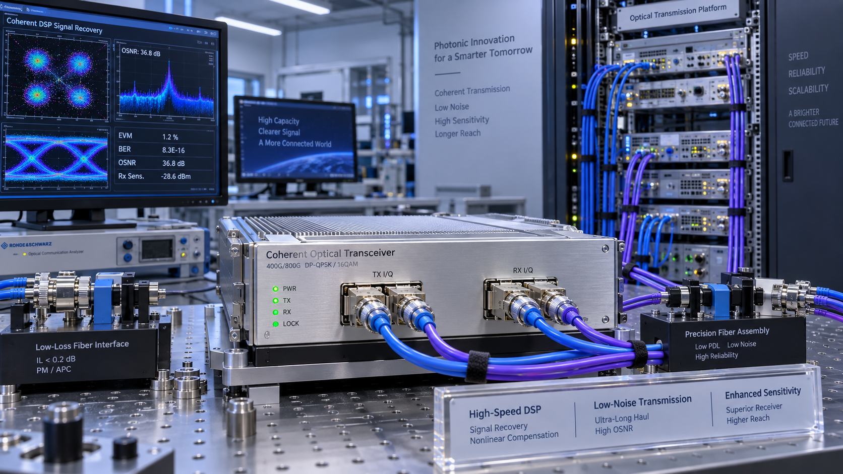
Electro-optic response is rarely a standalone buying decision. It intersects with laser beam quality, optical coatings, detector sensitivity, imaging geometry, fiber coupling, data acquisition, and thermal management. A fast gate may solve background suppression in a time-of-flight instrument, while a better coating stack or detector choice addresses another part of the same signal-to-noise problem. A fast modulator in a telecom path must be assessed alongside coherent transceivers, amplification, dispersion management, and the physical link budget.
This broader view is central to the work covered by Global Optics, Lasers & Electro-optic Systems (OLES). Its focus spans industrial lasers, machine vision, LiDAR components, optical coatings, specialty fibers, photonic communications, and electro-optic control. That combination is useful because the practical question is usually not whether a component is fast in isolation, but whether it supports a stable and manufacturable system.
Faster switching response is justified when it protects timing accuracy, preserves waveform integrity, or enables an optical measurement or process that slower control cannot support. The final selection should be based on the full timing budget, not the shortest number on a datasheet. Confirm optical and electrical test conditions, evaluate off-state behavior and repeatability, and leave realistic margin for integration. That is the difference between specifying a fast device and building an electro-optic system that remains fast where it matters.
- machine vision
- LiDAR components
- optical coatings
- industrial lasers
- electro-optic systems
- optical communications
- laser safety
- laser applications
- laser systems
- Time-of-Flight sensing
- beam quality
- Industrial Machine Vision
- coherent transceivers
- laser beam quality
- Dispersion Management
- Optical Alignment
- electro optic systems
Recommended News
 Non-linear Optics & ThermalLaser Thermal Management Suppliers: Verifying Temperature Stability Under LoadChoose a laser thermal management supplier with proven temperature stability under load. Learn how to verify cooling capacity, test transients, and compare evidence before you buy.Oct 13, 2026Author:Prof. Kaelen Sterling
 Area Scan CamerasHow to Evaluate a Machine Vision Technology Supplier for Long-Term Production SupportEvaluate a Machine Vision Technology supplier for lifecycle stability, change control, quality records, and responsive support to protect production continuity.Oct 12, 2026Author:Machine Vision Optical Expert
 3D Laser ProfilersHow to Select a 3D Laser Profiler for Inline Dimensional Inspection3D laser profilers metrology guide: learn how to select the right profiler for reliable inline dimensional inspection, surface challenges, throughput, and automation integration.Oct 11, 2026Author:Machine Vision Optical Expert
 FMCW Laser Sources1550 nm LiDAR Core Components: How Lasers, Detectors, and Optics Determine RangeLiDAR core components 1550nm explained: discover how lasers, InGaAs detectors, and precision optics shape long-range performance, reliability, and real-world sensing results.Oct 10, 2026Author:LiDAR Systems Fellow
 FMCW Laser SourcesSelecting 1550 nm Laser Diodes for Fiber-Optic Sensing and LiDAR Systems1550nm laser diodes: discover how to select stable, high-performance sources for fiber-optic sensing and LiDAR, from linewidth and pulse power to reliability.Oct 09, 2026Author:LiDAR Systems Fellow
 Optical TransceiversOptical Component Testing: Key Measurements for Reliable System IntegrationOptical Component Testing: explore essential spectral, wavefront, beam, and environmental measurements to ensure reliable integration, minimize risk, and improve system performance.Oct 08, 2026Author:Photonics Strategist
 Narrowband/IR Cut FiltersHow to Select Dielectric Thin-Film Longpass Filters by Edge Wavelength and AOIDielectric thin films longpass filters: learn how edge wavelength, AOI, polarization, and blocking range affect optical performance—select with confidence.Oct 07, 2026Author:Optical Coating Scientist
 Optical TransceiversHow MSA Standards Help Engineers Select Compatible Optical TransceiversOptical Transceivers MSA standards help engineers verify form factor, host, power, and optical link compatibility. Use this practical guide to select with confidence.Oct 06, 2026Author:Photonics Strategist
 Optical TransceiversCoherent Optical Communication Price: What Drives 400G and 800G Upgrade Costs?Coherent optical communication price explained: compare 400G and 800G upgrade costs, reach, power, compatibility, and lifecycle value for smarter network investments.Oct 05, 2026Author:Photonics Strategist
 Area Scan CamerasHow Multispectral Imaging Inspection Detects Defects Beyond RGB VisionMultispectral imaging inspection detects hidden defects beyond RGB vision, revealing moisture, oil, coating variation, and material differences for smarter quality control.Oct 04, 2026Author:Machine Vision Optical Expert
 Opto-Capital & Vision EconOptical Component Vendor Qualification: A Risk-Based Checklist for Procurement TeamsOptical component supply chain vendor qualification: use a risk-based checklist to assess quality controls, traceability, production continuity, and sourcing risk.Oct 03, 2026Author:Mr. Orion Cross
 Narrowband/IR Cut FiltersOptical Filter Durability: Choosing Dielectric Thin-Film MaterialsDielectric thin film materials determine optical filter durability. Explore how material pairs, deposition quality, substrates, and validation protect spectral performance in demanding environments.Oct 02, 2026Author:Optical Coating Scientist
 Silicon Photonics OPAPhotonic Sensor Design for LiDAR: Key Trade-Offs in Range, Resolution, and CostPhotonic sensor design for LiDAR: explore the critical trade-offs in range, resolution, wavelength, receiver performance, and cost for reliable, scalable sensing systems.Oct 01, 2026Author:LiDAR Systems Fellow
 Optical TransceiversOptical DSP Algorithms: Improving Receiver Sensitivity in Coherent TransceiversDSP algorithms optics improve coherent transceiver receiver sensitivity through dispersion compensation, polarization equalization, phase recovery, and FEC—assess reach, OSNR, and link margin.Sep 30, 2026Author:Photonics Strategist
 Non-linear Optics & ThermalSelecting Low-Loss Infrared Optical Components for High-Power Laser SystemsInfrared optical components low loss: learn how to select materials, coatings, and mounts that protect beam quality, reduce thermal risk, and improve laser uptime.Sep 29, 2026Author:Prof. Kaelen Sterling
 Area Scan CamerasWhat to Evaluate When Sourcing Optoelectronic Sensors for German Factory AutomationOptoelectronic Sensors Germany: learn how to evaluate detection reliability, PLC and IO-Link integration, environmental protection, lifecycle cost, and supplier support for dependable factory automation.Sep 28, 2026Author:Machine Vision Optical Expert
 Area Scan CamerasSelecting Industrial Automation Imaging Cameras for High-Speed Inspection LinesIndustrial automation imaging camera selection guide for high-speed inspection lines—compare resolution, shutters, lighting, optics, and data flow for reliable defect detection.Sep 27, 2026Author:Machine Vision Optical Expert
 PM & Radiation-hard FibersHow Submarine Optical Cables Are Designed to Withstand Deep-Sea Pressure and FaultsSubmarine optical cables are engineered to withstand deep-sea pressure, route hazards, and faults. Explore layered protection, monitoring, and repair strategies.Sep 26, 2026Author:Photonics Strategist
 3D Laser ProfilersTime-of-Flight Technology Standards: Accuracy, Safety, and Interoperability RequirementsTime-of-flight technology standards explained: compare accuracy, laser safety, functional safety, and interoperability requirements for reliable ToF deployment.Sep 25, 2026Author:Machine Vision Optical Expert
 3D Laser ProfilersBeam Diagnostics for M² Measurement: Methods, Accuracy Limits, and Setup ChoicesBeam diagnostics M2 measurement explained: compare ISO-aligned methods, accuracy limits, and setup choices to qualify lasers, reduce risk, and improve optical performance.Sep 24, 2026Author:Machine Vision Optical Expert