Laser Thermal Management Suppliers: Verifying Temperature Stability Under Load
A cooling system can hold its setpoint at idle and still let a laser overheat during production. Choosing a laser thermal management supplier therefore requires evidence that temperatures remain within acceptable limits at the laser’s critical components under representative loads. Rated cooling capacity and a stable display reading are useful starting points, but neither proves that the installed system will control heat where it matters.
The strongest supplier evaluation connects three things: the laser’s thermal requirements, a clearly defined operating profile, and measurements that show both steady operation and responses to changing loads. Without that connection, apparently comparable specifications can describe very different performance.
Define what must stay stable before comparing suppliers
“Temperature stability” needs a measurement location, an allowable variation, and a time period. A supplier may quote stability at the chiller outlet while the application requires control at a diode mount, gain medium, or optical assembly. Temperature changes between those locations depend on coolant flow, thermal resistance, component geometry, and heat generation.
Separate accuracy, stability, and uniformity. Accuracy describes how closely the measured temperature matches the intended value. Stability describes variation over time. Uniformity describes differences between locations. A cooling loop can be stable while operating at the wrong temperature, and its outlet can remain stable while different parts of a laser develop uneven temperatures.
Set acceptance limits from the laser’s operating requirements and process sensitivity. Diode temperature can affect emission wavelength; thermal gradients can affect alignment and optical performance. Where these effects matter, temperature measurements should be paired with relevant optical measurements. There is no universal temperature tolerance that makes every laser application reliable.
Compare cooling capacity at your operating conditions
A headline capacity rating is meaningful only alongside its test conditions. Available cooling capacity can change with coolant setpoint, ambient temperature, facility-water conditions, and coolant composition. Request performance curves covering the intended operating range, including the hottest expected environment and the required coolant temperature.
Build the heat-load estimate around heat entering the cooling circuit. Laser optical output is not interchangeable with waste heat. Electrical losses, pump sources, electronics, and other cooled components may contribute differently, and some heat may leave through other paths. Identify which loads share the loop and which operate simultaneously.
For liquid cooling, compare the pump curve with the complete circuit’s pressure loss. Hoses, filters, connectors, cold plates, and elevation changes influence delivered flow. Adequate refrigeration capacity cannot compensate for insufficient flow through a restrictive laser head. Conversely, increasing flow indiscriminately can exceed component pressure limits or introduce vibration.
Capacity reserve should cover credible changes in operating conditions and integration uncertainty. Ask the supplier to explain how the proposed system behaves at partial load as well as full load; an oversized unit with unsuitable control behavior may cycle or produce unnecessary temperature fluctuations.
Use a load profile that exposes transient problems
A constant-load demonstration shows only part of the cooling system’s behavior. Cutting, welding, inspection, and pulsed laser applications can involve repeated starts, pauses, and changing duty cycles. The test should reproduce the thermal load associated with those operating patterns. Electrical pulse frequency alone does not define the thermal response because the assembly stores and transfers heat over time.
Give shortlisted suppliers the same test profile so their results can be compared:
- Startup: Record the approach to operating temperature and establish when laser operation can begin.
- Sustained maximum load: Continue until temperatures settle, then check for drift during an extended run.
- Load changes: Apply representative increases and decreases to reveal overshoot, undershoot, and recovery behavior.
- Repeated duty cycles: Look for heat accumulation or oscillation across successive production cycles.
- Environmental limits: Repeat relevant conditions at the expected ambient or facility-water boundaries.
Define recovery as returning to, and remaining within, the acceptable temperature band. A trace that briefly crosses the setpoint has not necessarily settled. Record the largest excursion and how long the component remains outside its permitted range.
Heater-based testing can help compare systems before a laser is available, but heater placement and thermal mass affect the result. Use it to establish cooling capability, then validate the installed assembly before accepting application-level performance.
Measure beyond the controller’s sensor
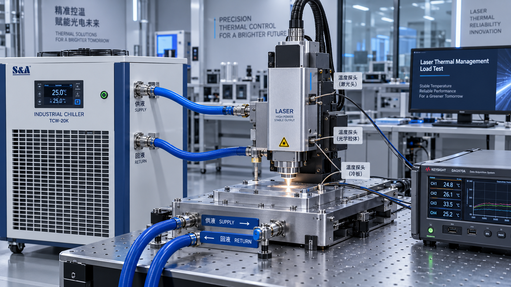
The controller measures the point used for regulation, which may be inside a reservoir or near the coolant outlet. Independent measurements should include coolant supply and return temperatures and accessible locations close to thermally sensitive components. Together, these readings help distinguish refrigeration limitations from poor heat transfer within the assembly.
Sensor installation deserves scrutiny. A loosely attached surface probe may respond slowly or track surrounding air. Contact quality, insulation, sensor response, and placement influence what the trace represents. If direct component measurement is impractical, document the proxy location and its relationship to the temperature being controlled.
Request calibration information and measurement uncertainty appropriate to the proposed acceptance band. When uncertainty approaches the permitted variation, the data cannot confidently demonstrate compliance. Logging intervals must also capture the transients of interest, and temperature, load, flow, and alarm records should use synchronized timestamps.
Inspect unfiltered data as well as presentation plots. Averaging can conceal short excursions, while an auto-scaled graph can make significant variation appear small. Compressor cycles, valve movements, or interactions between temperature controllers may become visible only when the full timeline is examined.
Evaluate the installed system and the evidence package
Integration can change an otherwise satisfactory result. Confirm coolant compatibility with wetted materials, seals, and the laser manufacturer’s requirements. Fluid composition affects heat transfer and hydraulic behavior. Filtration, corrosion control, maintenance access, and contamination management also influence whether initial performance can be maintained.
Check condensation risk whenever cooled surfaces may fall below the surrounding air’s dew point. A lower setpoint can improve one thermal condition while creating moisture problems elsewhere. The proposed installation should address insulation, humidity conditions, and any required dew-point control.
Ask how low flow, excessive temperature, sensor failure, and cooling interruption reach the laser’s interlock system. Fault-response testing should demonstrate an agreed protective response under controlled conditions. A local alarm has limited value if the laser continues generating heat without receiving it.
The supplier’s evidence package should identify the tested configuration, coolant, ambient conditions, load profile, sensor locations, measurement uncertainty, control settings, and raw time-series data. Performance guarantees should reference that configuration, with commissioning responsibilities and acceptance criteria documented.
Shortlist suppliers whose results match the intended installation and whose engineers can explain observed excursions. Before placing an order, resolve any gap between outlet-temperature claims and component-temperature requirements. The purchasing decision should rest on demonstrated thermal behavior throughout the operating cycle, supported by a repeatable acceptance test.
Recommended News
 Non-linear Optics & ThermalLaser Thermal Management Suppliers: Verifying Temperature Stability Under LoadChoose a laser thermal management supplier with proven temperature stability under load. Learn how to verify cooling capacity, test transients, and compare evidence before you buy.Oct 13, 2026Author:Prof. Kaelen Sterling
 Area Scan CamerasHow to Evaluate a Machine Vision Technology Supplier for Long-Term Production SupportEvaluate a Machine Vision Technology supplier for lifecycle stability, change control, quality records, and responsive support to protect production continuity.Oct 12, 2026Author:Machine Vision Optical Expert
 3D Laser ProfilersHow to Select a 3D Laser Profiler for Inline Dimensional Inspection3D laser profilers metrology guide: learn how to select the right profiler for reliable inline dimensional inspection, surface challenges, throughput, and automation integration.Oct 11, 2026Author:Machine Vision Optical Expert
 FMCW Laser Sources1550 nm LiDAR Core Components: How Lasers, Detectors, and Optics Determine RangeLiDAR core components 1550nm explained: discover how lasers, InGaAs detectors, and precision optics shape long-range performance, reliability, and real-world sensing results.Oct 10, 2026Author:LiDAR Systems Fellow
 FMCW Laser SourcesSelecting 1550 nm Laser Diodes for Fiber-Optic Sensing and LiDAR Systems1550nm laser diodes: discover how to select stable, high-performance sources for fiber-optic sensing and LiDAR, from linewidth and pulse power to reliability.Oct 09, 2026Author:LiDAR Systems Fellow
 Optical TransceiversOptical Component Testing: Key Measurements for Reliable System IntegrationOptical Component Testing: explore essential spectral, wavefront, beam, and environmental measurements to ensure reliable integration, minimize risk, and improve system performance.Oct 08, 2026Author:Photonics Strategist
 Narrowband/IR Cut FiltersHow to Select Dielectric Thin-Film Longpass Filters by Edge Wavelength and AOIDielectric thin films longpass filters: learn how edge wavelength, AOI, polarization, and blocking range affect optical performance—select with confidence.Oct 07, 2026Author:Optical Coating Scientist
 Optical TransceiversHow MSA Standards Help Engineers Select Compatible Optical TransceiversOptical Transceivers MSA standards help engineers verify form factor, host, power, and optical link compatibility. Use this practical guide to select with confidence.Oct 06, 2026Author:Photonics Strategist
 Optical TransceiversCoherent Optical Communication Price: What Drives 400G and 800G Upgrade Costs?Coherent optical communication price explained: compare 400G and 800G upgrade costs, reach, power, compatibility, and lifecycle value for smarter network investments.Oct 05, 2026Author:Photonics Strategist
 Area Scan CamerasHow Multispectral Imaging Inspection Detects Defects Beyond RGB VisionMultispectral imaging inspection detects hidden defects beyond RGB vision, revealing moisture, oil, coating variation, and material differences for smarter quality control.Oct 04, 2026Author:Machine Vision Optical Expert
 Opto-Capital & Vision EconOptical Component Vendor Qualification: A Risk-Based Checklist for Procurement TeamsOptical component supply chain vendor qualification: use a risk-based checklist to assess quality controls, traceability, production continuity, and sourcing risk.Oct 03, 2026Author:Mr. Orion Cross
 Narrowband/IR Cut FiltersOptical Filter Durability: Choosing Dielectric Thin-Film MaterialsDielectric thin film materials determine optical filter durability. Explore how material pairs, deposition quality, substrates, and validation protect spectral performance in demanding environments.Oct 02, 2026Author:Optical Coating Scientist
 Silicon Photonics OPAPhotonic Sensor Design for LiDAR: Key Trade-Offs in Range, Resolution, and CostPhotonic sensor design for LiDAR: explore the critical trade-offs in range, resolution, wavelength, receiver performance, and cost for reliable, scalable sensing systems.Oct 01, 2026Author:LiDAR Systems Fellow
 Optical TransceiversOptical DSP Algorithms: Improving Receiver Sensitivity in Coherent TransceiversDSP algorithms optics improve coherent transceiver receiver sensitivity through dispersion compensation, polarization equalization, phase recovery, and FEC—assess reach, OSNR, and link margin.Sep 30, 2026Author:Photonics Strategist
 Non-linear Optics & ThermalSelecting Low-Loss Infrared Optical Components for High-Power Laser SystemsInfrared optical components low loss: learn how to select materials, coatings, and mounts that protect beam quality, reduce thermal risk, and improve laser uptime.Sep 29, 2026Author:Prof. Kaelen Sterling
 Area Scan CamerasWhat to Evaluate When Sourcing Optoelectronic Sensors for German Factory AutomationOptoelectronic Sensors Germany: learn how to evaluate detection reliability, PLC and IO-Link integration, environmental protection, lifecycle cost, and supplier support for dependable factory automation.Sep 28, 2026Author:Machine Vision Optical Expert
 Area Scan CamerasSelecting Industrial Automation Imaging Cameras for High-Speed Inspection LinesIndustrial automation imaging camera selection guide for high-speed inspection lines—compare resolution, shutters, lighting, optics, and data flow for reliable defect detection.Sep 27, 2026Author:Machine Vision Optical Expert
 PM & Radiation-hard FibersHow Submarine Optical Cables Are Designed to Withstand Deep-Sea Pressure and FaultsSubmarine optical cables are engineered to withstand deep-sea pressure, route hazards, and faults. Explore layered protection, monitoring, and repair strategies.Sep 26, 2026Author:Photonics Strategist
 3D Laser ProfilersTime-of-Flight Technology Standards: Accuracy, Safety, and Interoperability RequirementsTime-of-flight technology standards explained: compare accuracy, laser safety, functional safety, and interoperability requirements for reliable ToF deployment.Sep 25, 2026Author:Machine Vision Optical Expert
 3D Laser ProfilersBeam Diagnostics for M² Measurement: Methods, Accuracy Limits, and Setup ChoicesBeam diagnostics M2 measurement explained: compare ISO-aligned methods, accuracy limits, and setup choices to qualify lasers, reduce risk, and improve optical performance.Sep 24, 2026Author:Machine Vision Optical Expert