How Do Optical Materials Affect Laser Damage Resistance?
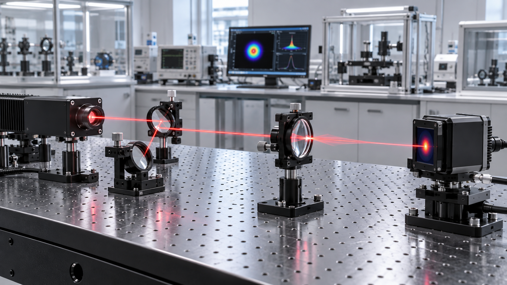
Optical material choice sets the practical ceiling for laser damage resistance because the material determines how much laser energy is absorbed, how quickly heat is removed, how defects grow, and whether the surface or bulk can tolerate the local electric field. A component with excellent transmission at low power can still fail rapidly under a tightly focused, pulsed, or high-average-power beam. The relevant question is therefore not whether a material is broadly “laser resistant,” but whether its absorption, structure, finish, coating stack, and mounting arrangement fit the actual wavelength, pulse format, beam size, and operating environment.
Laser-induced damage usually begins at a localized weak point rather than across an ideal optical surface. A polishing pit, subsurface fracture, contamination particle, coating nodule, residual stress zone, or microscopic inclusion can absorb more energy than the surrounding material. That small region heats or ionizes first. Once the surface morphology changes, scattering and absorption often rise, accelerating the damage process on subsequent pulses. Material selection affects both the probability of initiating that event and the rate at which it spreads.
Damage resistance is tied to the laser regime
A laser damage threshold is meaningful only when the test conditions resemble the intended use. Nanosecond pulses, ultrashort pulses, continuous-wave beams, and burst-mode sources deposit energy through different mechanisms. A material that handles a high continuous power level may fail under a short pulse with lower average power because the peak intensity is far higher. Conversely, an optic that survives isolated pulses may overheat during long-duration exposure when absorbed energy accumulates faster than it can leave the aperture.
Wavelength changes the decision as well. An optical glass may show low absorption in the visible or near-infrared band yet absorb strongly at a harmonic wavelength, in the ultraviolet, or in the mid-infrared. The same applies to coatings, bonding layers, and surface contamination. A nominally transparent optic should therefore be evaluated by its spectral absorption near the operating wavelength, including nearby wavelengths that can appear through nonlinear conversion, back-reflection, or alignment drift.
Beam geometry is equally important. Damage is driven by local fluence or intensity, not merely total laser output. Reducing the beam diameter by a factor of two raises the energy density substantially at the optic. Hot spots in a nonuniform beam, clipping at a small clear aperture, and tight focusing at a window edge can invalidate a material choice that appeared adequate from average power alone.
Absorption turns optical loss into thermal stress
For continuous-wave and high-repetition-rate laser systems, low absorption is often the first material requirement. Even a small absorption coefficient can generate a serious thermal load when power density is high. Temperature gradients then create refractive-index gradients, surface deformation, birefringence in stress-sensitive materials, or fracture. In transmissive components, the risk is not limited to the front face: bulk absorption can produce an internal heat zone that is difficult to detect before beam distortion appears.
Fused silica is widely used where low absorption, good homogeneity, and strong resistance to thermal shock are required over much of the ultraviolet, visible, and near-infrared spectrum. Its low thermal expansion helps limit stress caused by uneven heating. However, fused silica is not automatically suitable for every high-power path. Hydroxyl content, impurity level, radiation exposure, solarization behavior, surface quality, and the wavelength-dependent absorption profile all matter. At demanding ultraviolet conditions, compaction, color-center formation, and surface contamination can progressively alter performance.
Sapphire offers high hardness, high thermal conductivity relative to many glasses, and robust mechanical behavior. These traits can make it attractive for protective windows and components exposed to harsh handling or elevated temperatures. Its crystalline nature also introduces directional properties. Refractive index, thermal expansion, and stress response vary with crystal orientation, while birefringence can be unacceptable in polarization-sensitive paths. A sapphire window selected only for hardness may introduce wavefront or polarization effects that are more damaging to system performance than a less durable isotropic alternative.
Calcium fluoride, magnesium fluoride, zinc selenide, silicon, and other infrared materials each bring a distinct compromise among spectral transmission, thermal conductivity, expansion, hardness, hygroscopic sensitivity, and fracture behavior. A mid-infrared material cannot be judged by visible-light handling rules. Some infrared optics are comparatively soft, have lower thermal-shock tolerance, or require particular cleaning methods. Mechanical durability, coating compatibility, and mounting stress deserve the same attention as transmission.

Bulk quality and surface condition are separate variables
A material data sheet often describes an ideal bulk property, while laser damage frequently originates at the processed surface. The polishing route can leave subsurface damage beneath an apparently smooth finish. Microcracks and embedded polishing residues become absorptive sites, especially under ultraviolet radiation or high peak fluence. Scratch-dig notation alone does not fully predict this behavior because it describes visible surface defects rather than the full distribution of subsurface fractures, pits, contamination, and local stress.
Edge quality matters when the clear aperture is used aggressively. Chamfers with chips, coating roll-off near the edge, and mounting features close to the illuminated region can create localized scatter. In a focused beam path, a small defect outside the nominal beam footprint may still matter if alignment changes or thermal lensing shifts the beam. Clear-aperture margin is a practical damage-control measure, not merely a drawing convenience.
Cleaning can either preserve or undermine the selected material. Residues from adhesives, gloves, packaging, pump oils, fingerprints, and unsuitable solvents absorb laser energy far more readily than a clean optical substrate. Some coatings and crystal surfaces are also vulnerable to abrasive wiping. A cleaning method should account for coating adhesion, material softness, water sensitivity, and the likelihood that repeated handling causes micro-scratches. Persistent damage at random locations often points to contamination or handling exposure rather than an intrinsic substrate limitation.
Coatings frequently define the real limit
For mirrors, polarizers, beam splitters, antireflection windows, and harmonic separators, the coating can be the damage-limiting element even when the substrate is highly resistant. Dielectric multilayers rely on alternating high- and low-index films. At certain field distributions, the electric-field intensity inside a particular layer can exceed the incident-field level. A coating designed for high reflectivity at one angle and polarization may have a different internal field pattern when used off angle or with the wrong polarization state.
Coating absorption is affected by deposition process, film density, stoichiometry, particulate defects, interface roughness, and post-deposition treatment. A dense, low-absorption dielectric stack generally tolerates laser exposure better than a porous or defective layer, but the stack design must also accommodate mechanical stress. Thick multilayer designs can accumulate stress, leading to cracking, delamination, or curvature changes under thermal cycling. The preferred coating is therefore not always the one with the highest nominal reflectance; it is the design with an appropriate spectral response and stable behavior at the required fluence, angle, polarization, and environmental load.
Metal coatings present a different tradeoff. They can provide broad spectral reflectance and avoid some narrowband design constraints, but absorption is often higher than in optimized dielectric mirrors. Under high average power, absorbed energy may heat the coating and its interface with the substrate. The adhesion layer, protective overcoat, and substrate thermal expansion can all influence whether the coating remains intact. Comparing a metal mirror and dielectric mirror by reflectance alone misses the thermal and field-distribution differences that govern service life.
Nonlinear crystals require a narrower operating window
Frequency-conversion crystals are exposed to high internal intensities by design, so their damage behavior cannot be separated from phase matching, beam focus, temperature control, and crystal orientation. Local absorption can generate thermal gradients that shift phase matching and reduce conversion efficiency. The resulting unconverted or distorted beam can change downstream fluence conditions, creating a failure sequence that appears to originate elsewhere in the optical train.
Some nonlinear materials are susceptible to moisture, surface degradation, photorefractive effects, or gray tracking under particular wavelengths and power densities. Others have limited acceptance angle or spatial walk-off that encourages use of a tighter beam than the crystal can comfortably tolerate. A large beam reduces fluence but may conflict with aperture, conversion efficiency, or uniform-temperature requirements. The workable design is usually found by balancing conversion performance against a conservative intensity margin, rather than maximizing conversion in a short test run.
Thermal expansion must match the assembled optic
An optic does not operate as an isolated coupon. Retaining rings, metal cells, adhesives, soldered joints, and cooling interfaces impose mechanical boundary conditions. A material with low bulk absorption can still distort or crack if its thermal expansion differs sharply from that of the mount and the assembly is constrained too tightly. Radial pressure from a retaining ring may be harmless at room temperature but become significant after localized heating. Conversely, a loose mount can allow tilt, vibration, or poor thermal contact.
Mount design should leave appropriate room for expansion, avoid point loading near the clear aperture, and prevent stress from entering a thin window or crystal. Where heat extraction is needed, interface quality and contact pressure matter. An aggressively cooled mount can create its own temperature gradient if cooling is uneven. Thermal management is therefore part of the material decision: a substrate with strong conductivity gains little if heat cannot pass effectively into the mechanical structure.
Interpreting damage evidence correctly
Different failure appearances point to different causes. A central crater near the beam waist often suggests excessive local fluence, a focal-position error, or a beam hot spot. Damage concentrated near an aperture edge can indicate clipping, edge defects, or mount-induced stress. A growing haze may arise from coating degradation, contamination burn-in, ultraviolet exposure, or a roughened surface that is now scattering more light. Circular rings or broad distortions without visible pitting can indicate thermal lensing before permanent damage is obvious.
Replacing an optic without identifying the failure pattern often repeats the same outcome. The incident beam profile, polarization, pulse duration, repetition rate, angle of incidence, optic orientation, purge condition, and upstream back-reflections should be reviewed together. A rear-surface defect, for example, may be caused by a focused ghost reflection or contamination introduced during assembly rather than the nominal transmitted beam.
Specify material performance as a usable operating envelope
Material selection becomes more reliable when the requirement is written as an operating envelope instead of a single damage-threshold value. The specification should identify laser wavelength, spectral bandwidth where relevant, pulse duration, repetition rate, beam diameter at the optic, expected polarization, angle of incidence, clear aperture, average power, peak fluence or intensity, and exposure duration. It should also distinguish the substrate requirement from the coating requirement and state whether both faces see laser radiation.
- A high-average-power transmissive window needs absorption and thermal-distortion information, not only a pulsed damage figure.
- For a short-pulse mirror, the coating test conditions, polarization, and incidence angle are often more informative than the substrate name.
- When a crystal is involved, specify the beam waist location, intended temperature range, orientation, and whether the beam is continuous, pulsed, or burst-mode.
- Where contamination is credible, include cleanliness, handling, packaging, and inspection expectations because an otherwise suitable optic can fail from an avoidable surface absorber.
Laser damage resistance is ultimately a system property expressed through material behavior. Low absorption, high thermal conductivity, low expansion, good polish quality, stable coatings, and suitable mounting all improve the margin, but none substitutes for matching the optic to the actual laser field. The most durable optical choice is the one whose limitations remain outside the expected operating envelope throughout alignment, thermal cycling, and repeated exposure.
Recommended News
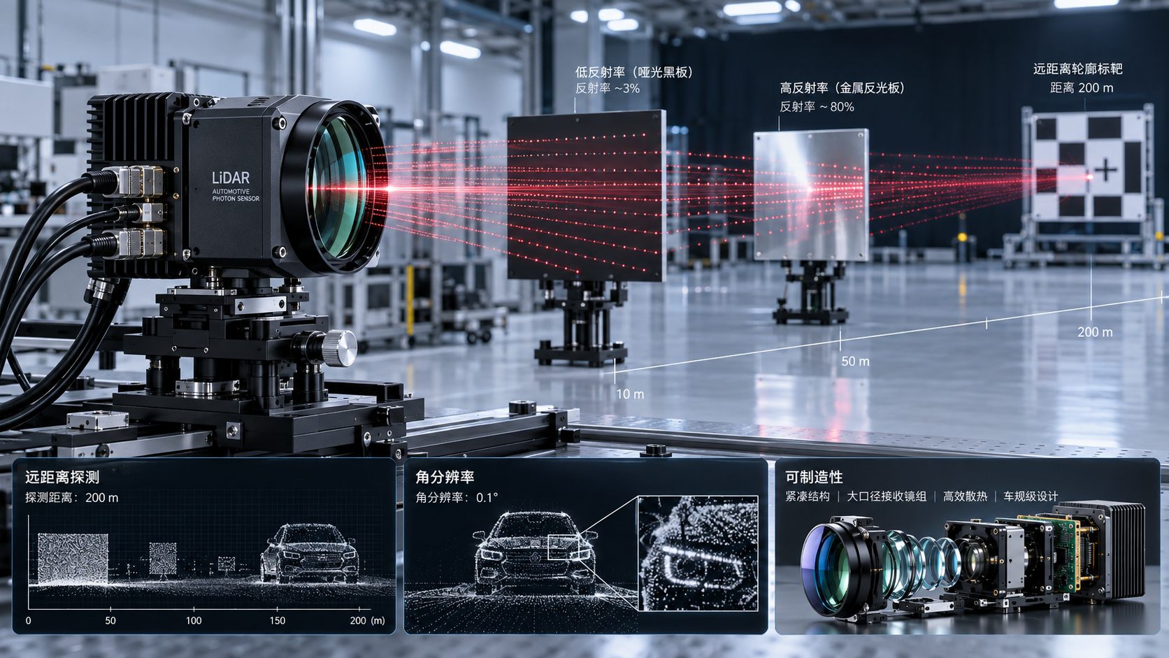
 Silicon Photonics OPAPhotonic Sensor Design for LiDAR: Key Trade-Offs in Range, Resolution, and CostPhotonic sensor design for LiDAR: explore the critical trade-offs in range, resolution, wavelength, receiver performance, and cost for reliable, scalable sensing systems.Oct 01, 2026Author:LiDAR Systems Fellow
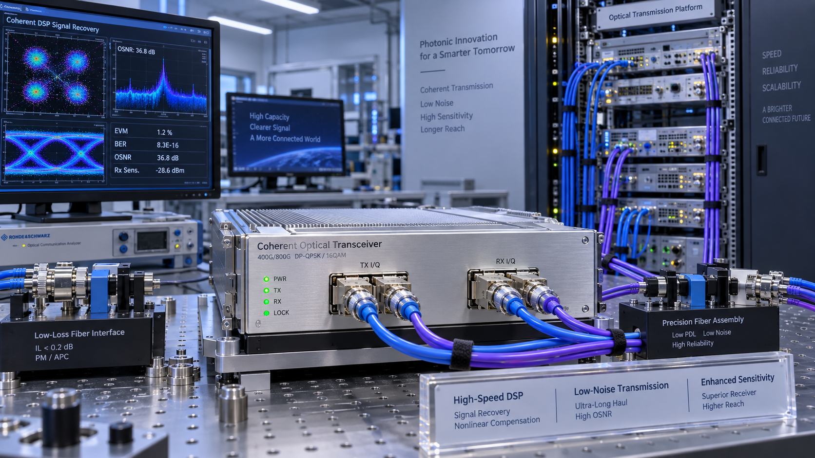
 Optical TransceiversOptical DSP Algorithms: Improving Receiver Sensitivity in Coherent TransceiversDSP algorithms optics improve coherent transceiver receiver sensitivity through dispersion compensation, polarization equalization, phase recovery, and FEC—assess reach, OSNR, and link margin.Sep 30, 2026Author:Photonics Strategist
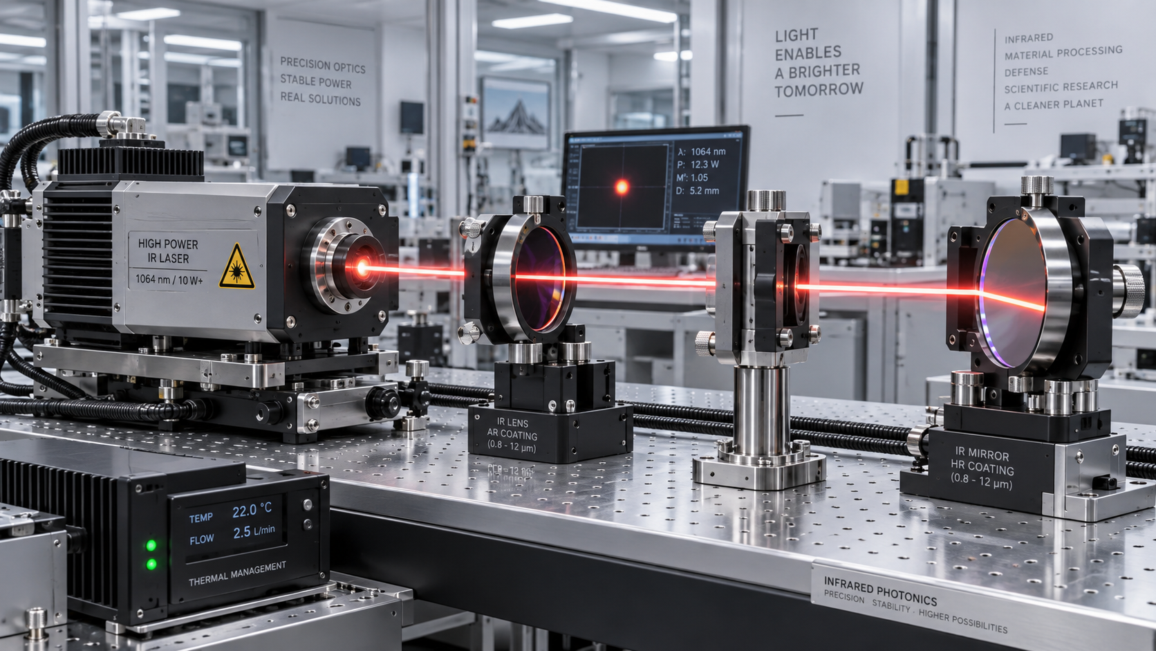
 Non-linear Optics & ThermalSelecting Low-Loss Infrared Optical Components for High-Power Laser SystemsInfrared optical components low loss: learn how to select materials, coatings, and mounts that protect beam quality, reduce thermal risk, and improve laser uptime.Sep 29, 2026Author:Prof. Kaelen Sterling
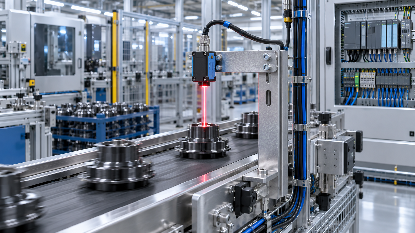
 Area Scan CamerasWhat to Evaluate When Sourcing Optoelectronic Sensors for German Factory AutomationOptoelectronic Sensors Germany: learn how to evaluate detection reliability, PLC and IO-Link integration, environmental protection, lifecycle cost, and supplier support for dependable factory automation.Sep 28, 2026Author:Machine Vision Optical Expert
 Area Scan CamerasSelecting Industrial Automation Imaging Cameras for High-Speed Inspection LinesIndustrial automation imaging camera selection guide for high-speed inspection lines—compare resolution, shutters, lighting, optics, and data flow for reliable defect detection.Sep 27, 2026Author:Machine Vision Optical Expert
 PM & Radiation-hard FibersHow Submarine Optical Cables Are Designed to Withstand Deep-Sea Pressure and FaultsSubmarine optical cables are engineered to withstand deep-sea pressure, route hazards, and faults. Explore layered protection, monitoring, and repair strategies.Sep 26, 2026Author:Photonics Strategist
 3D Laser ProfilersTime-of-Flight Technology Standards: Accuracy, Safety, and Interoperability RequirementsTime-of-flight technology standards explained: compare accuracy, laser safety, functional safety, and interoperability requirements for reliable ToF deployment.Sep 25, 2026Author:Machine Vision Optical Expert
 3D Laser ProfilersBeam Diagnostics for M² Measurement: Methods, Accuracy Limits, and Setup ChoicesBeam diagnostics M2 measurement explained: compare ISO-aligned methods, accuracy limits, and setup choices to qualify lasers, reduce risk, and improve optical performance.Sep 24, 2026Author:Machine Vision Optical Expert
![]() Non-linear Optics & ThermalHow Do Optical Materials Affect Laser Damage Resistance?How do optical material choices affect laser damage resistance? Explore absorption, coatings, thermal stress, and material selection for reliable high-power laser optics.Sep 24, 2026Author:Prof. Kaelen Sterling
Non-linear Optics & ThermalHow Do Optical Materials Affect Laser Damage Resistance?How do optical material choices affect laser damage resistance? Explore absorption, coatings, thermal stress, and material selection for reliable high-power laser optics.Sep 24, 2026Author:Prof. Kaelen Sterling![]() Narrowband/IR Cut FiltersWhich Optical Coating Is Best for Stray Light Suppression?Which optical coating is best for stray light suppression? Compare broadband AR, V-coatings, and black absorptive finishes to improve contrast, reduce flare, and protect system performance.Sep 24, 2026Author:Optical Coating Scientist
Narrowband/IR Cut FiltersWhich Optical Coating Is Best for Stray Light Suppression?Which optical coating is best for stray light suppression? Compare broadband AR, V-coatings, and black absorptive finishes to improve contrast, reduce flare, and protect system performance.Sep 24, 2026Author:Optical Coating Scientist![]() PM & Radiation-hard FibersWhen Should a Fiber Optic Sensor Be Replaced?When should a fiber optic sensor be replaced? Learn the warning signs, from signal drift and unstable switching to damage, calibration failure, and lost optical margin.Sep 24, 2026Author:Photonics Strategist
PM & Radiation-hard FibersWhen Should a Fiber Optic Sensor Be Replaced?When should a fiber optic sensor be replaced? Learn the warning signs, from signal drift and unstable switching to damage, calibration failure, and lost optical margin.Sep 24, 2026Author:Photonics Strategist![]() 3D Laser ProfilersHow Accurate Is Time-of-Flight Sensing for Industrial Measurement?How accurate is Time-of-Flight sensing for industrial measurement? Explore real-world accuracy factors, applications, and validation tips for reliable ToF performance.Sep 24, 2026Author:Machine Vision Optical Expert
3D Laser ProfilersHow Accurate Is Time-of-Flight Sensing for Industrial Measurement?How accurate is Time-of-Flight sensing for industrial measurement? Explore real-world accuracy factors, applications, and validation tips for reliable ToF performance.Sep 24, 2026Author:Machine Vision Optical Expert![]() FMCW Laser SourcesIs 1550 nm LiDAR Better for Long-Range, Low-Light Sensing?Is 1550nm LiDAR better for long-range low-light sensing? Explore eye-safe power, range potential, detector trade-offs, weather limits, and how to choose the right LiDAR architecture.Sep 24, 2026Author:LiDAR Systems Fellow
FMCW Laser SourcesIs 1550 nm LiDAR Better for Long-Range, Low-Light Sensing?Is 1550nm LiDAR better for long-range low-light sensing? Explore eye-safe power, range potential, detector trade-offs, weather limits, and how to choose the right LiDAR architecture.Sep 24, 2026Author:LiDAR Systems Fellow![]() Telecentric LensesWhat Causes Distortion in Industrial Machine Vision Lenses?What causes distortion in industrial machine vision lenses? Discover key optical, sensor, and setup factors—and how to improve inspection accuracy.Sep 24, 2026Author:Machine Vision Optical Expert
Telecentric LensesWhat Causes Distortion in Industrial Machine Vision Lenses?What causes distortion in industrial machine vision lenses? Discover key optical, sensor, and setup factors—and how to improve inspection accuracy.Sep 24, 2026Author:Machine Vision Optical Expert![]() Area Scan CamerasHow Can Machine Vision Detect Micron-Level Surface Defects?How can machine vision detect micron-level surface defects? Explore optics, lighting, resolution, AI, and calibration strategies for reliable, high-speed inspection.Sep 24, 2026Author:Machine Vision Optical Expert
Area Scan CamerasHow Can Machine Vision Detect Micron-Level Surface Defects?How can machine vision detect micron-level surface defects? Explore optics, lighting, resolution, AI, and calibration strategies for reliable, high-speed inspection.Sep 24, 2026Author:Machine Vision Optical Expert Optical TransceiversSelecting High-Speed Optical Transceivers for 400G and 800G Data Center LinksOptical transceivers high speed selection for 400G and 800G data centers: compare fiber, reach, thermal limits, interoperability, and breakout strategies for reliable scaling.Sep 23, 2026Author:Photonics Strategist
 PM & Radiation-hard FibersSelecting Specialty Optical Fibers for High-Power, Sensing, and Harsh EnvironmentsSpecialty Optical Fibers selection guide for high-power delivery, precision sensing, and harsh environments. Compare performance, reliability, and integration factors.Sep 22, 2026Author:Photonics Strategist
 Non-linear Optics & ThermalHow to Evaluate Laser Thermal Management Suppliers for High-Power SystemsLaser thermal management supplier evaluation guide for high-power systems: compare thermal control, reliability, scalability, and lifecycle cost.Sep 21, 2026Author:Prof. Kaelen Sterling
 FMCW Laser SourcesHow to Evaluate Laser Stability Suppliers for Precision Measurement SystemsChoose a laser stability supplier with confidence. Learn how to assess stability, integration, acceptance testing, and supply continuity for precision measurement systems.Sep 20, 2026Author:LiDAR Systems Fellow
 FMCW Laser SourcesLaser Stability Monitoring: Which Metrics Reveal Drift Before It Disrupts Production?Laser stability monitoring reveals early drift through power, beam pointing, focus, pulse energy, and thermal trends—helping prevent defects and production downtime.Sep 19, 2026Author:LiDAR Systems Fellow